ISRO Workshop: Day 3
Day 1: resonant bodies and stochastic timing drove point accumulation. Day 2: rhythm machines drove structural graphics through topology, physics, and composite buffers. Today: shaders. Data crosses from CPU to GPU through three mechanisms of increasing power. By the end, the GPU computes geometry from audio parameters with zero CPU position updates.
Day 3 has three parts, twelve examples. Each part introduces a different mechanism for sending data to shaders.
Part 1: Push Constants (A through E)
Small structs (up to ~128 bytes) sent to the shader every frame. Manual at first, then automated via NodeBindingsProcessor. Image, camera, and video sources.
Part 2: Descriptor Bindings / SSBO (F through H) Large data (hundreds to thousands of floats) uploaded as storage buffers. The shader reads arrays directly. Delay network histories, modal spectra, network outputs.
Part 3: GPU Geometry (I through L)
Vertices are created with placeholder positions. The vertex shader computes actual positions from push constants and gl_VertexIndex. The CPU never touches position data after initialization.
Part 1: Push Constants
Tutorial: Static Tint
Original: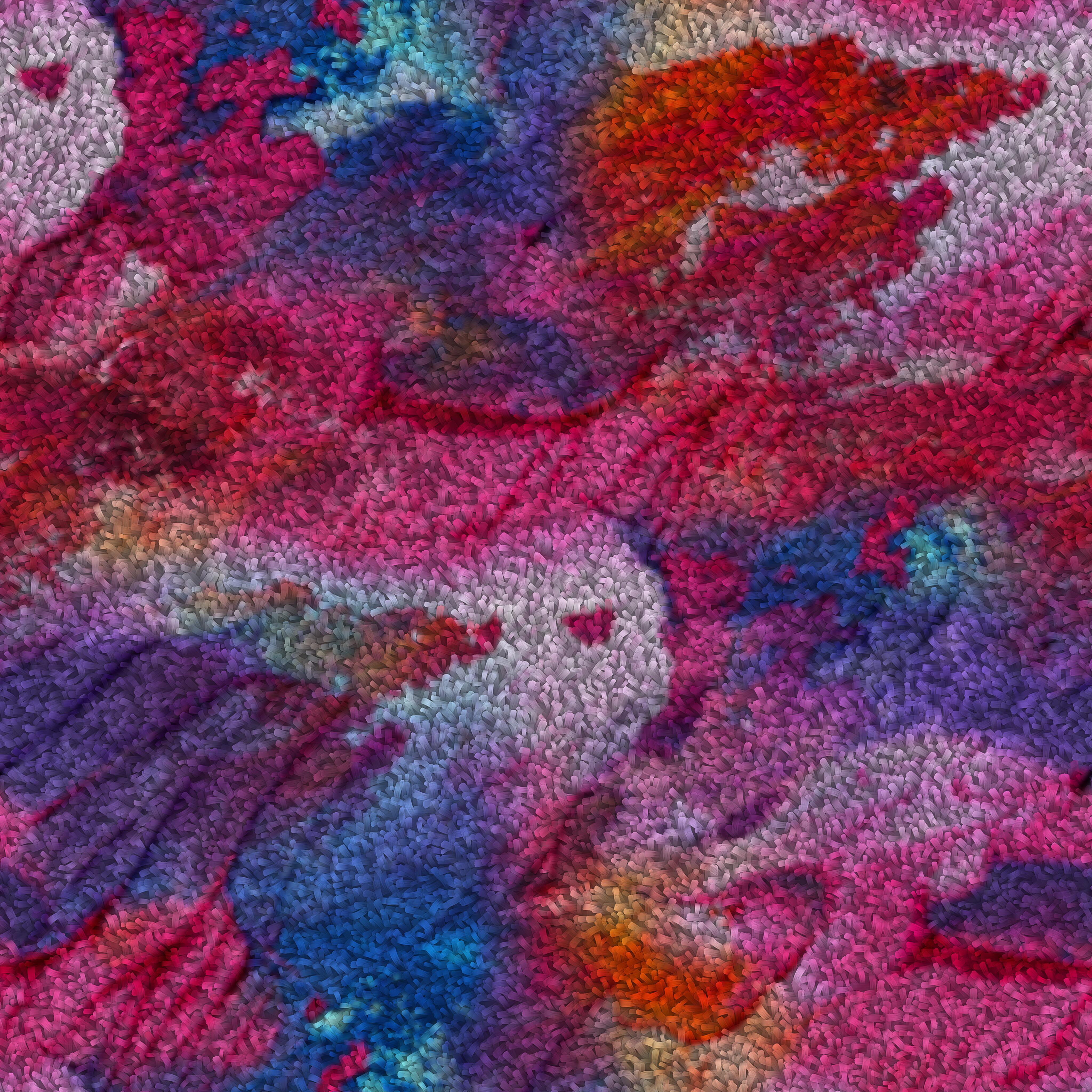
void compose() { day3_a_static_tint(); }
Run this. An image appears with a pink tint. Nothing moves. The shader receives four floats (tint_r, tint_g, tint_b, brightness) as push constants and multiplies the texture color by them.
Change the numbers in the Params struct. Rebuild. The tint changes. This is the entire mechanism: a C++ struct maps byte-for-byte to a GLSL layout(push_constant) uniform block.
Expansion: Push constant mechanics
struct Params {
    float tint_r;
    float tint_g;
    float tint_b;
    float brightness;
};
rp->set_push_constant_size<Params>();
rp->set_push_constant_data(p);
set_push_constant_size<T>() tells the pipeline how many bytes to reserve. set_push_constant_data(p) copies the struct into the command buffer before each draw call. The shader reads it:
layout(push_constant) uniform Params {
    float tint_r, tint_g, tint_b, brightness;
};
Push constants are limited to 128 bytes on most hardware (256 on some). They are the fastest path for small, frequently-changing data. No buffer allocation, no descriptor set updates.
Tutorial: First Crossing
void compose() { day3_b_first_crossing(); }
Run this. The image warps back and forth. A 2 Hz sine oscillator drives warp_amount in the push constants. A schedule_metro(0.016, ...) callback reads the node’s last output and pushes the updated struct every frame.
This is the manual approach: you own the metro, you build the struct, you push it. It works, but it scales poorly when you have many parameters.
Tutorial: Dual Stream (NodeBindingsProcessor)
void compose() { day3_c_dual_stream(); }
Run this. An image is displaced along two independent axes. Stream A is a recursive delay network producing interference patterns. Stream B is non-linear probability shaping. Both are bound to separate push constant fields via NodeBindingsProcessor.
Expansion: NodeBindingsProcessor
auto node_bindings = std::make_shared<Buffers::NodeBindingsProcessor>(shader_config);
node_bindings->bind_node("a", delay_net, offsetof(Params, displacement_a), sizeof(float));
NodeBindingsProcessor replaces the manual metro pattern. You declare which node maps to which byte offset in the push constant struct. Every frame, the processor reads each node’s get_last_output(), casts to float, and writes it into the push constant buffer at the declared offset.
No metro callback. No manual struct construction. You declare bindings once and the processor handles the rest.
The Constant node provides fixed values cleanly:
auto aspect = vega.Constant(16.0 / 9.0) | Graphics;
node_bindings->bind_node("aspect", aspect, offsetof(Params, aspect), sizeof(float));
This replaces the lambda-wrapped Polynomial pattern vega.Polynomial([](double) { return 16.0/9.0; }) from older code. Constant is zero-overhead: no coefficients, no history buffer, just a number.
Tutorial: Breathing Geometry
void compose() { day3_d_breathing_geometry(); }
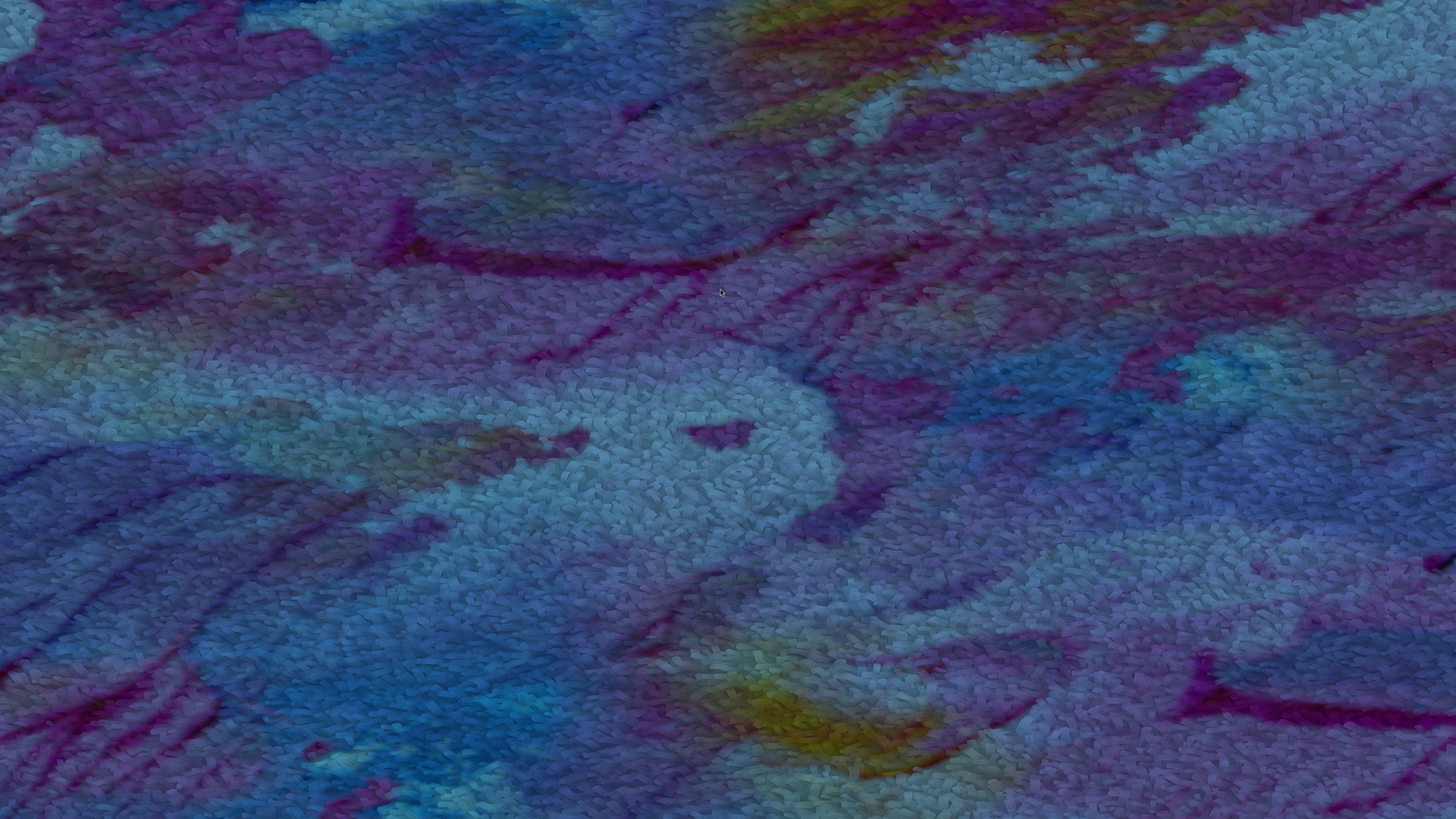
Run this. The image quad itself deforms. A recursive delay line resonates. Its envelope (full-wave rectified amplitude) drives a vertex shader that displaces the quad corners. The geometry breathes with the audio.
This is the first example where push constants drive a vertex shader, not a fragment shader. The same NodeBindingsProcessor mechanism, different shader stage.
Tutorial: Polar Warp (Camera)
void compose() { day3_e_polar_warp(); }
Run this. Your camera feed is distorted through polar coordinates. Three independent modulation streams control radial scale, angular velocity, and chromatic aberration split.
Expansion: Camera as texture source
auto manager = get_io_manager();
auto camera = manager->open_camera({
    .device_name = "/dev/video0",
    .target_width = 1920, .target_height = 1080, .target_fps = 30 });
auto tex = manager->hook_camera_to_buffer(camera);
tex->setup_rendering({ .target_window = window, .fragment_shader = "polar_warp.frag" });
IOManager::open_camera() opens the device via FFmpeg, creates a CameraContainer, and starts a background decode thread. hook_camera_to_buffer() creates a VideoContainerBuffer that the graphics subsystem processes every frame: new camera frame → GPU texture upload → fragment shader reads it via sampler2D.
From the shader’s perspective, a camera frame is identical to a static image. The only difference is that the texture data changes every frame. All push constant and descriptor binding mechanisms work identically regardless of whether the texture source is a file, a camera, or a video.
On macOS, use "0" (AVFoundation device index) instead of "/dev/video0".
Part 2: Descriptor Bindings (SSBO)
Push constants max out at 128 to 256 bytes. When you need to send hundreds or thousands of values per frame, you use storage buffers (SSBO) via descriptor bindings.
Tutorial: History Field (Camera + SSBO)
void compose() { day3_f_history_field(); }
Run this. Your camera feed ripples. A recursive delay network generates audio. Its entire 400-sample history buffer is uploaded to the GPU as a storage buffer every frame. The fragment shader reads history.values[int(uv.y * sample_count)] and uses it to displace uv.x. The ripple pattern is the internal state of the delay network, made visible.
Expansion: DescriptorBindingsProcessor
auto shader_config = Buffers::ShaderConfig { "hist_field.frag" };
shader_config.bindings["history_data"] = Buffers::ShaderBinding(0, 1, vk::DescriptorType::eStorageBuffer);

auto desc_bindings = std::make_shared<Buffers::DescriptorBindingsProcessor>(shader_config);
desc_bindings->bind_vector_node("history", delay_net, "history_data", 0,
    Portal::Graphics::DescriptorRole::STORAGE,
    Buffers::DescriptorBindingsProcessor::ProcessingMode::EXTERNAL);
ShaderConfig::bindings declares descriptor set layouts: which binding slot, which descriptor type. DescriptorBindingsProcessor::bind_vector_node() connects a node’s output buffer (the Polynomial’s internal history) to that slot. Every frame, the processor reads the node’s GPU-compatible float buffer and uploads it to a VkBuffer bound at set=0, binding=1.
The shader receives it as:
layout(set = 0, binding = 1) buffer HistoryData { float values[]; } history;
An unbounded array of floats. The shader indexes into it freely. No size limit beyond GPU memory.
Push constants and descriptor bindings coexist: the same buffer can have both a NodeBindingsProcessor (for small parameters like sample_count and intensity) and a DescriptorBindingsProcessor (for the large history array).
set_gpu_compatible(true) on the node enables the float conversion path that bind_vector_node requires.
Tutorial: Audio Input Field (Video File + Audio Input SSBO)
void compose() { day3_g_audio_input_field(); }
Run this. A video file plays, distorted by your microphone input. The live audio buffer (512 samples from the input listener) is bound directly to the shader as an SSBO. The fragment shader reads the waveform and uses it as a 1D displacement map across the image height. Speak, clap, or play an instrument into the mic: the video ripples with the waveform shape.
Expansion: bind_audio_buffer
auto buf = create_input_listener_buffer(0);
desc_bindings->bind_audio_buffer("history", buf, "history_data", 0);
create_input_listener_buffer(0) captures live audio from channel 0 of the system’s input device. The buffer fills with 512 samples per processing cycle. bind_audio_buffer() connects that buffer directly to a descriptor binding slot.
No node extraction. No manual copying. No intermediate Polynomial wrapper. The audio buffer IS the data. Every frame, the processor reads the buffer’s current contents and uploads them as a storage buffer. The shader receives the raw waveform.
This is the most direct path from physical sound to GPU data. Microphone → buffer → SSBO → fragment shader. Four links, no transformation. The shader decides how to interpret the numbers.
Compare the three SSBO binding methods used so far:
bind_vector_node()(History Field): reads a node’s internal history buffer. Good for recursive delay networks whose state is the content.bind_audio_buffer()(this example): reads any audio buffer directly. Good for live input, file playback, or any buffer in the processing chain.bind_network()(Network Descriptor): reads a NodeNetwork’s mixed output. Good for synthesis networks where you want the final mix.
All three produce the same result at the GPU level: buffer HistoryData { float values[]; }. The difference is where the floats come from.
Tutorial: Network Descriptor (Camera + ResonatorNetwork SSBO)
void compose() { day3_h_network_descriptor(); }
Run this. Camera feed distorted by the output of a 5-formant ResonatorNetwork. The network’s mixed audio buffer is bound as an SSBO via bind_network(). The excitation source is switchable: Phasor (pitched), noise (breathy), WaveguideNetwork (string excites vocal tract), ModalNetwork (bell excites vocal tract). Vowel presets (A/E/I/O/U) switch formant profiles live.
Expansion: bind_network vs bind_vector_node
desc_bindings->bind_network("history", rn, "history_data", 0);
bind_network() is a convenience method for NodeNetwork instances. It reads the network’s mixed output buffer (get_audio_buffer()) and uploads it as a storage buffer. This is the network-level equivalent of bind_vector_node() for individual nodes.
The key difference: a single ResonatorNetwork contains 5 internal IIR filters, an exciter, and a mixing stage. bind_network() gives the shader the final mixed result. If you wanted per-resonator data, you would use bind_structured_node() with a mode extractor (as in the Modal Rings example).
Expansion: Excitation source switching
The ResonatorNetwork accepts three levels of excitation:
set_exciter(node): single node drives all resonators simultaneouslyset_resonator_exciter(index, node): per-resonator individual excitersset_network_exciter(network): another NodeNetwork provides per-resonator signals
Switching happens live:
on_key_pressed(window, IO::Keys::N1, [rn, exciter]() {
    rn->clear_network_exciter();
    rn->set_exciter(exciter);       // Phasor: pitched, buzzy
});
on_key_pressed(window, IO::Keys::N2, [rn, wv]() {
    rn->clear_exciter();
    rn->set_network_exciter(wv);    // WaveguideNetwork: string pluck excites vocal tract
});
A plucked string exciting a vocal tract is not a metaphor. The waveguide network outputs audio samples. The resonator network filters them through formant peaks. The GPU shader sees the result as 400 floats per frame. The same pipeline, different input.
Part 3: GPU Geometry
Everything until now sent data to fragment or vertex shaders that operated on existing geometry (image quads, pre-positioned points). Now the vertex shader computes positions from scratch. The CPU provides placeholder vertices with glm::vec3(0.0) positions. The shader uses gl_VertexIndex and push constants to place them.
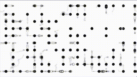
Tutorial: Phasor Ring
void compose() { day3_i_phasor_ring(); }
Run this. Click to strike a bell. 360 points form a pulsing ring. The vertex shader positions each point on a circle based on its index, then modulates the radius with audio energy and a slow sine oscillator. The CPU never updates positions.
Expansion: GPU-only positioning
// phasor_ring.vert (simplified)
float angle = float(gl_VertexIndex) / 360.0 * 6.28318;
float r = 0.5 + radius_mod * 0.2 + energy * 0.3;
gl_Position = vec4(cos(angle) * r / aspect, sin(angle) * r, 0.0, 1.0);
360 vertices are created on the CPU with glm::vec3(0.0) positions. The vertex shader ignores those positions entirely. It uses gl_VertexIndex to determine where each point belongs on the ring, and push constants (time, radius_mod, energy, aspect) to control the ring’s shape.
The CPU contribution is: colors and sizes (set once at initialization) and push constant values (updated every frame via NodeBindingsProcessor). All position computation happens on the GPU.
This is the pattern for all GPU geometry examples: the CPU declares intent (how many vertices, what colors), the GPU computes spatial arrangement.
Tutorial: Wave Mesh
void compose() { day3_j_wave_mesh(); }
Run this. A 6400-point grid undulates. The vertex shader computes sine wave displacements along both axes. Audio energy from a resonator controls wave amplitude. Slow LFOs drift the wave frequencies. The mesh breathes and ripples without a single CPU position update.
Tutorial: Orbit Cloud
void compose() { day3_k_orbit_cloud(); }
Run this. Click to strike a bell. 1000 points orbit in elliptical paths. Each orbit’s semi-major axis, eccentricity, and inclination are derived from gl_VertexIndex. Audio energy contracts all orbits (gravitational pulse). Spectral centroid tilts the orbital plane. A recursive delay network adds angular jitter.
Expansion: Spectral centroid as shader parameter
schedule_metro(0.016, [bell, orbit_state]() {
    const auto& modes = bell->get_modes();
    double weighted = 0.0;
    double total = 0.0;
    for (const auto& m : modes) {
        weighted += m.frequency_ratio * m.amplitude;
        total += m.amplitude;
    }
    orbit_state->centroid_tilt.store(
        static_cast<float>(total > 0.001 ? (weighted / total) * 0.3 : 0.0), ...);
});
The spectral centroid is the amplitude-weighted average of frequency ratios across all modes. When high modes dominate (bright timbre), the centroid is high, and the orbital plane tilts more. When low modes dominate (dark timbre), the plane flattens. A physical property of the sound (spectral balance) becomes a geometric property of the visualization (orbital tilt).
This is computed on the CPU (reading mode data from the ModalNetwork) and passed to the GPU as a single float push constant. The vertex shader applies it as a rotation matrix to all orbit positions.
Tutorial: IFS Tree
void compose() { day3_l_ifs_tree(); }
Run this. Click or press Space to strike. A fractal tree grows, breathes, and bends with audio. 2048 vertices are positioned by an iterated function system in the vertex shader. Each vertex encodes a path through a binary tree: at each depth level, the shader applies either a left-branch or right-branch affine transformation based on bit masks of gl_VertexIndex.
Push constants control branch angle, scale factor, trunk bend, and audio energy. Slow LFOs modulate angle and scale. The tree sways continuously. Audio strikes cause the canopy to expand (energy drives scale and brightness).
Day 3 Summary
Twelve examples. Three mechanisms for data transit from CPU to GPU.
Push Constants (A through E):
- Struct → GPU. Up to 128 bytes. Fastest path.
- Manual: build struct in metro callback, push every frame.
- Automated:
NodeBindingsProcessordeclares node → offset mappings. One declaration, automatic updates. Constantnode replaces lambda-wrapped Polynomials for fixed values.- Works with vertex shaders (geometry deformation) and fragment shaders (texture distortion).
Descriptor Bindings / SSBO (F through H):
- Large arrays → GPU. Hundreds to thousands of floats per frame.
DescriptorBindingsProcessoruploads node histories, audio buffers, network outputs.bind_vector_node(): single node’s GPU-compatible float buffer (delay network history).bind_audio_buffer(): any audio buffer directly (input listener, container buffer, file playback).bind_network(): NodeNetwork’s mixed audio output (ResonatorNetwork, WaveguideNetwork).- Coexists with push constants on the same buffer.
GPU Geometry (I through L):
- Vertex shader computes positions from
gl_VertexIndex+ push constants. - CPU provides placeholder vertices (colors, sizes). GPU computes spatial arrangement.
- Zero CPU position updates after initialization.
- Scales to thousands of vertices with negligible CPU cost.
Input sources used:
- Static image (
vega.read_image) - Live camera (
manager->open_camera+hook_camera_to_buffer) - Video file (
manager->load_video+hook_video_container_to_buffer)
All three produce a sampler2D in the shader. The binding mechanism is identical regardless of source. A camera frame, a video frame, and a static image are the same thing to the GPU: a texture that may or may not change between frames.
Conceptual shift from Day 2: Day 2 computed everything on the CPU: point positions, topology connections, physics forces. The GPU received finished vertex data and drew it. Day 3 moves computation to the GPU: the shader reads raw audio parameters and computes geometry, distortion, and visual structure itself. The CPU’s role reduces to: generate audio, extract parameters, push them across.